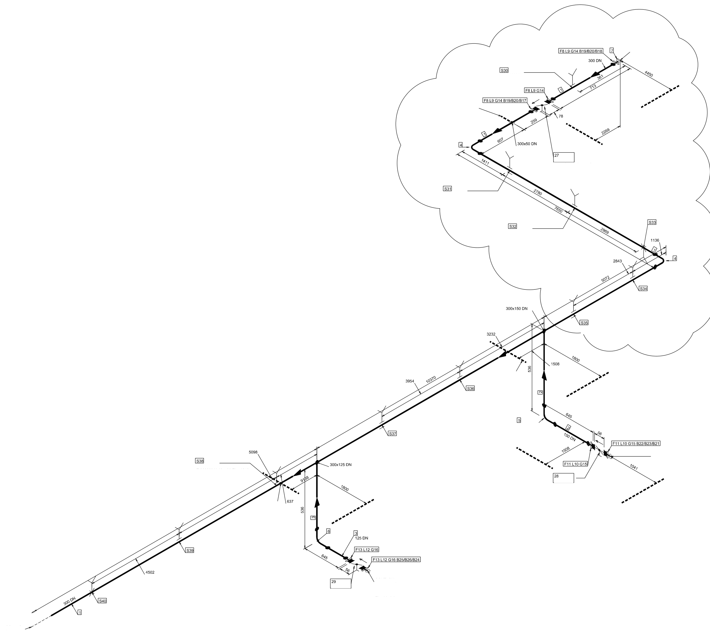
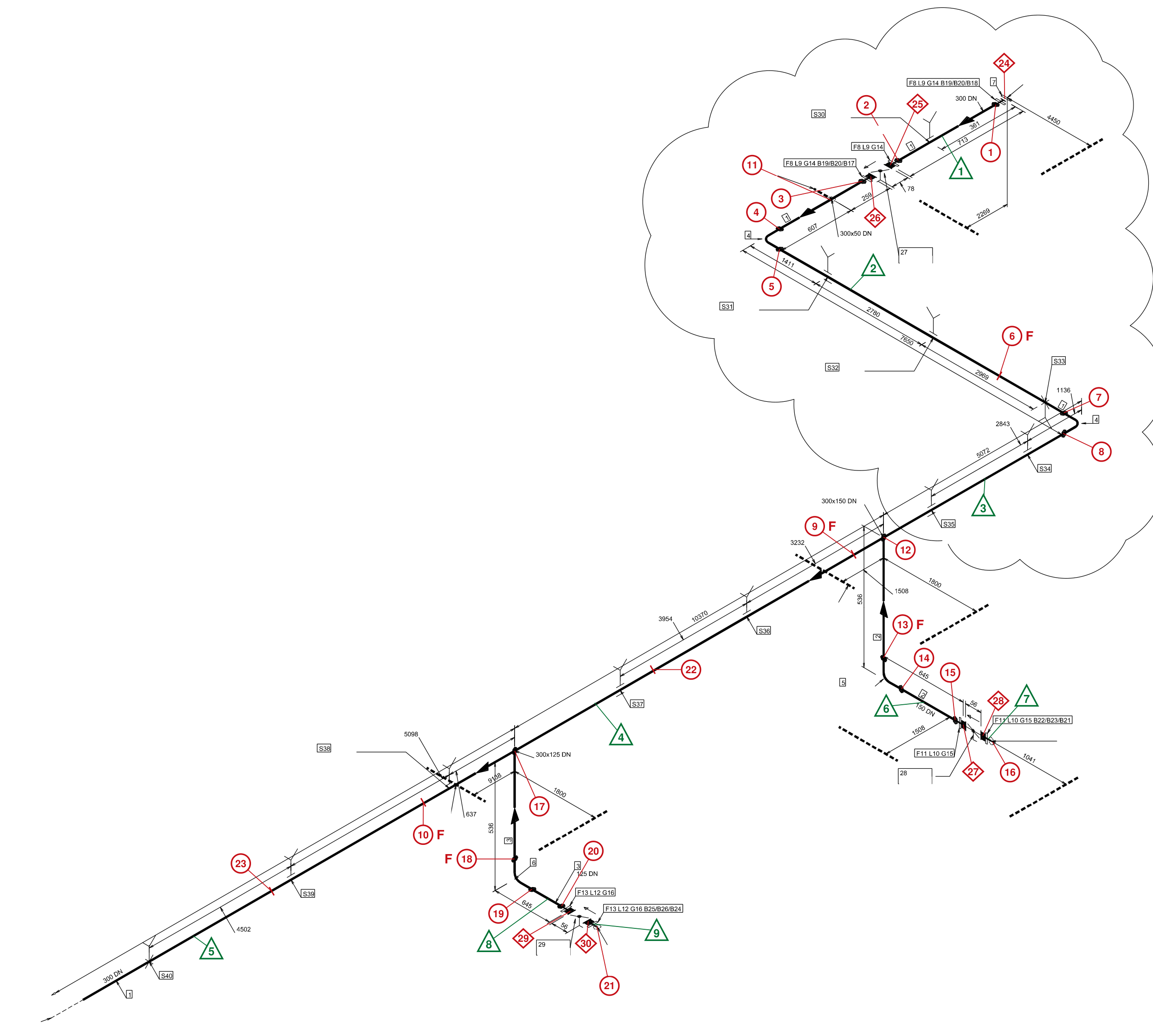
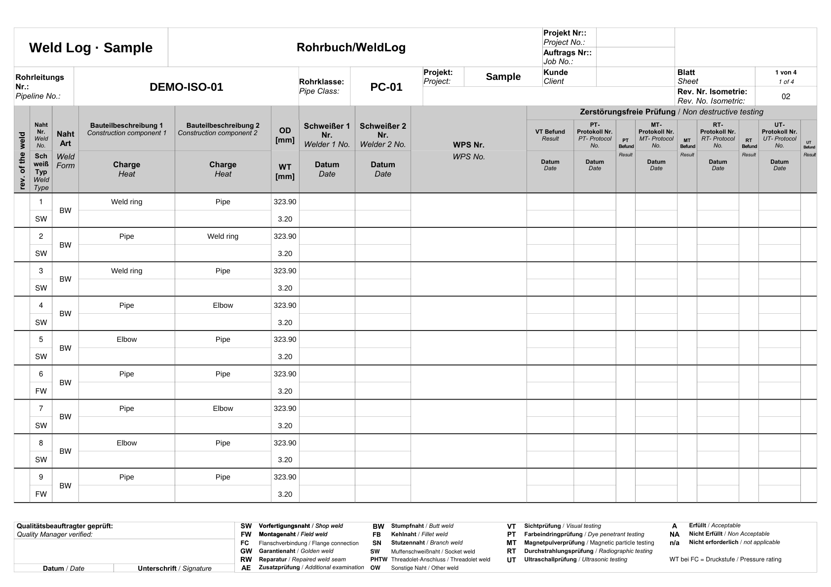
| DEMO000001 | Process cooling water 30 °C | DEMO-ISO-01 | 02 | 1 | SEP | PC-01 | PCW | 1 | SW | BW | 300 | 323.9 | 3.2 | 141 | 141-Test0000001 | | | | | | | Type 35 weld ring DN 300 (item 9) | Weld ring | 1.4432 | | Pipe DN 300 (item 1) | Pipe | 1.4432 | | Component 2 wall thickness recorded. Component 1 is open. |
| DEMO000001 | Process cooling water 30 °C | DEMO-ISO-01 | 02 | 1 | SEP | PC-01 | PCW | 2 | SW | BW | 300 | 323.9 | 3.2 | 141 | 141-Test0000001 | | | | | | | Pipe DN 300 (item 1) | Pipe | 1.4432 | | Type 35 weld ring DN 300 (item 9) | Weld ring | 1.4432 | | Component 1 wall thickness recorded. Component 2 is open. |
| DEMO000001 | Process cooling water 30 °C | DEMO-ISO-01 | 02 | 1 | SEP | PC-01 | PCW | 3 | SW | BW | 300 | 323.9 | 3.2 | 141 | 141-Test0000001 | | | | | | | Type 35 weld ring DN 300 (item 9) | Weld ring | 1.4432 | | Pipe DN 300 (item 1) | Pipe | 1.4432 | | Component 2 wall thickness recorded. Component 1 is open. |
| DEMO000001 | Process cooling water 30 °C | DEMO-ISO-01 | 02 | 1 | SEP | PC-01 | PCW | 4 | SW | BW | 300 | 323.9 | 3.2 | 141 | 141-Test0000001 | | | | | | | Pipe DN 300 (item 1) | Pipe | 1.4432 | | Type A-3D elbow DN 300 (item 4) | Elbow | 1.4432 | | Component 1 (item 1) wall thickness 3.2 mm, component 2 (item 4) 4.0 mm. |
| DEMO000001 | Process cooling water 30 °C | DEMO-ISO-01 | 02 | 1 | SEP | PC-01 | PCW | 5 | SW | BW | 300 | 323.9 | 3.2 | 141 | 141-Test0000001 | | | | | | | Type A-3D elbow DN 300 (item 4) | Elbow | 1.4432 | | Pipe DN 300 (item 1) | Pipe | 1.4432 | | Component 1 (item 4) wall thickness 4.0 mm, component 2 (item 1) 3.2 mm. |
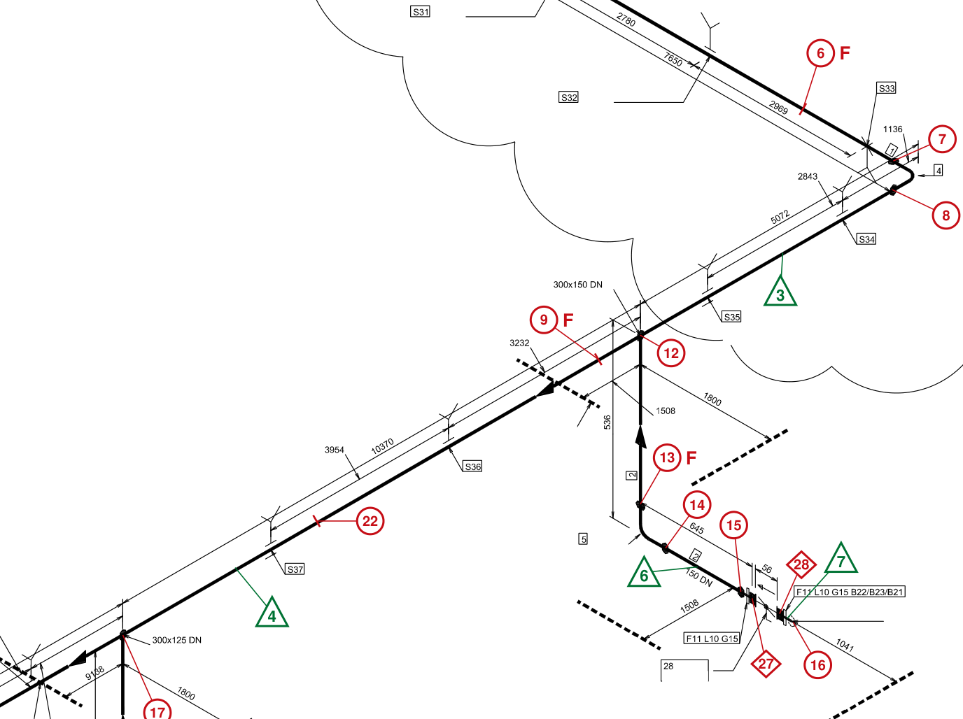
| DEMO000001 | Process cooling water 30 °C | DEMO-ISO-01 | 02 | 1 | SEP | PC-01 | PCW | 6 | FW | BW | 300 | 323.9 | 3.2 | 141 | 141-Test0000001 | | | | | | | Pipe DN 300 (item 1) | Pipe | 1.4432 | | Pipe DN 300 (item 1) | Pipe | 1.4432 | | X (E/W), DN 300. 1,759 mm west of S32. Spools 2 and 3. |
| DEMO000001 | Process cooling water 30 °C | DEMO-ISO-01 | 02 | 1 | SEP | PC-01 | PCW | 7 | SW | BW | 300 | 323.9 | 3.2 | 141 | 141-Test0000001 | | | | | | | Pipe DN 300 (item 1) | Pipe | 1.4432 | | Type A-3D elbow DN 300 (item 4) | Elbow | 1.4432 | | Component 1 (item 1) wall thickness 3.2 mm, component 2 (item 4) 4.0 mm. |
| DEMO000001 | Process cooling water 30 °C | DEMO-ISO-01 | 02 | 1 | SEP | PC-01 | PCW | 8 | SW | BW | 300 | 323.9 | 3.2 | 141 | 141-Test0000001 | | | | | | | Type A-3D elbow DN 300 (item 4) | Elbow | 1.4432 | | Pipe DN 300 (item 1) | Pipe | 1.4432 | | Component 1 (item 4) wall thickness 4.0 mm, component 2 (item 1) 3.2 mm. |
| DEMO000001 | Process cooling water 30 °C | DEMO-ISO-01 | 02 | 1 | SEP | PC-01 | PCW | 9 | FW | BW | 300 | 323.9 | 3.2 | 141 | 141-Test0000001 | | | | | | | Pipe DN 300 (item 1) | Pipe | 1.4432 | | Pipe DN 300 (item 1) | Pipe | 1.4432 | | Y (N/S), DN 300. 1,800 mm north of S35. Spools 3 and 4. |
| DEMO000001 | Process cooling water 30 °C | DEMO-ISO-01 | 02 | 1 | SEP | PC-01 | PCW | 10 | FW | BW | 300 | 323.9 | 3.2 | 141 | 141-Test0000001 | | | | | | | Pipe DN 300 (item 1) | Pipe | 1.4432 | | Pipe DN 300 (item 1) | Pipe | 1.4432 | | Y (N/S), DN 300. 800 mm north of S38. Spools 4 and 5. |
| DEMO000001 | Process cooling water 30 °C | DEMO-ISO-01 | 02 | 1 | SEP | PC-01 | PCW | 11 | SW | SN | 300 | 323.9 | 3.2 | 141 | 141-Test0000001 | | | | | | | Pipe DN 300 (item 1) | Pipe | 1.4432 | | Connection DN 50 · DEMO-ISO-02 | Connection | | | DN 300 × 50 reinforced. Direct branch connection assumed at the transition. Spool 2, connecting isometric DEMO-ISO-02. Component 1 OD and wall thickness recorded. Component 2 OD, wall thickness and material are open. |
| DEMO000001 | Process cooling water 30 °C | DEMO-ISO-01 | 02 | 1 | SEP | PC-01 | PCW | 12 | SW | SN | 300 | 323.9 | 2 | 141 | 141-Test0000001 | | | | | | | Pipe DN 300 (item 1) | Pipe | 1.4432 | | Pipe DN 150 (item 2) | Pipe | 1.4432 | | Direct-welded reinforced DN 300 × 150 branch. OD in component order 1 / 2. Component 1 (item 1) wall thickness 3.2 mm, component 2 (item 2) 2.0 mm. |
| DEMO000001 | Process cooling water 30 °C | DEMO-ISO-01 | 02 | 1 | SEP | PC-01 | PCW | 13 | FW | BW | 150 | 168.3 | 2 | 141 | 141-Test0000001 | | | | | | | Pipe DN 150 (item 2) | Pipe | 1.4432 | | Type A-3D elbow DN 150 (item 5) | Elbow | 1.4432 | | Z (vertical), DN 150. Joint between pipe item 2 and elbow item 5 above the elbow. Spools 3 and 6. Component 1 wall thickness 2.0 mm, component 2 2.6 mm. |
| DEMO000001 | Process cooling water 30 °C | DEMO-ISO-01 | 02 | 1 | SEP | PC-01 | PCW | 14 | SW | BW | 150 | 168.3 | 2 | 141 | 141-Test0000001 | | | | | | | Type A-3D elbow DN 150 (item 5) | Elbow | 1.4432 | | Pipe DN 150 (item 2) | Pipe | 1.4432 | | Component 1 (item 5) wall thickness 2.6 mm, component 2 (item 2) 2.0 mm. |
| DEMO000001 | Process cooling water 30 °C | DEMO-ISO-01 | 02 | 1 | SEP | PC-01 | PCW | 15 | SW | BW | 150 | 168.3 | 2 | 141 | 141-Test0000001 | | | | | | | Pipe DN 150 (item 2) | Pipe | 1.4432 | | Type 35 weld ring DN 150 (item 10) | Weld ring | 1.4432 | | Component 1 wall thickness recorded. Component 2 is open. |
| DEMO000001 | Process cooling water 30 °C | DEMO-ISO-01 | 02 | 1 | SEP | PC-01 | PCW | 16 | SW | BW | 150 | 168.3 | 2 | 141 | 141-Test0000001 | | | | | | | Type 35 weld ring DN 150 (item 10) | Weld ring | 1.4432 | | Connection DN 150 · DEMO-ISO-03 | Connection | | | Weld ring at the transition to DEMO-ISO-03. Weld assigned to sheet 1. Spool 7 continues. Component 1 OD recorded. Component 2 OD and material are open. Wall thicknesses are open on both sides. |
| DEMO000001 | Process cooling water 30 °C | DEMO-ISO-01 | 02 | 1 | SEP | PC-01 | PCW | 17 | SW | SN | 300 | 323.9 | 2 | 141 | 141-Test0000001 | | | | | | | Pipe DN 300 (item 1) | Pipe | 1.4432 | | Pipe DN 125 (item 3) | Pipe | 1.4432 | | Direct-welded reinforced DN 300 × 125 branch. OD in component order 1 / 2. Component 1 (item 1) wall thickness 3.2 mm, component 2 (item 3) 2.0 mm. |
| DEMO000001 | Process cooling water 30 °C | DEMO-ISO-01 | 02 | 1 | SEP | PC-01 | PCW | 18 | FW | BW | 125 | 139.7 | 2 | 141 | 141-Test0000001 | | | | | | | Pipe DN 125 (item 3) | Pipe | 1.4432 | | Type A-3D elbow DN 125 (item 6) | Elbow | 1.4432 | | Z (vertical), DN 125. Joint between pipe item 3 and elbow item 6 above the elbow. Spools 4 and 8. |
| DEMO000001 | Process cooling water 30 °C | DEMO-ISO-01 | 02 | 1 | SEP | PC-01 | PCW | 19 | SW | BW | 125 | 139.7 | 2 | 141 | 141-Test0000001 | | | | | | | Type A-3D elbow DN 125 (item 6) | Elbow | 1.4432 | | Pipe DN 125 (item 3) | Pipe | 1.4432 | | |
| DEMO000001 | Process cooling water 30 °C | DEMO-ISO-01 | 02 | 1 | SEP | PC-01 | PCW | 20 | SW | BW | 125 | 139.7 | 2 | 141 | 141-Test0000001 | | | | | | | Pipe DN 125 (item 3) | Pipe | 1.4432 | | Type 35 weld ring DN 125 (item 12) | Weld ring | 1.4432 | | Component 1 wall thickness recorded. Component 2 is open. |
| DEMO000001 | Process cooling water 30 °C | DEMO-ISO-01 | 02 | 1 | SEP | PC-01 | PCW | 21 | SW | BW | 125 | 139.7 | 2 | 141 | 141-Test0000001 | | | | | | | Type 35 weld ring DN 125 (item 12) | Weld ring | 1.4432 | | Connection DN 125 · DEMO-ISO-04 | Connection | | | Weld ring at the transition to DEMO-ISO-04. Weld assigned to sheet 1. Spool 9 continues. Component 1 OD recorded. Component 2 OD and material are open. Wall thicknesses are open on both sides. |
| DEMO000001 | Process cooling water 30 °C | DEMO-ISO-01 | 02 | 1 | SEP | PC-01 | PCW | 22 | SW | BW | 300 | 323.9 | 3.2 | 141 | 141-Test0000001 | | | | | | | Pipe DN 300 (item 1) | Pipe | 1.4432 | | Pipe DN 300 (item 1) | Pipe | 1.4432 | | 6 m pipe joint, spool 4. 1,029 mm south of S37. Pipe lengths of 5,450 and 5,650 mm. |
| DEMO000001 | Process cooling water 30 °C | DEMO-ISO-01 | 02 | 1 | SEP | PC-01 | PCW | 23 | SW | BW | 300 | 323.9 | 3.2 | 141 | 141-Test0000001 | | | | | | | Pipe DN 300 (item 1) | Pipe | 1.4432 | | Pipe DN 300 (item 1) | Pipe | 1.4432 | | 6 m pipe joint, spool 5. 602 mm north of S39. 4,900 mm from FW 10, 3,900 mm to S40. Continuation open. |
| DEMO000001 | Process cooling water 30 °C | DEMO-ISO-01 | 02 | 1 | SEP | PC-01 | PCW | 24 | FC | | 300 | 323.9 | PN 16 | 141 | 141-Test0000001 | | | | | | | Type 05B blind flange DN 300 (item 7) | Blind flange | | | Loose flange and weld ring (item 8/9) | Flange set | | | DN 300 blind flange to flange set, spool 1. Gasket item 14. |
| DEMO000001 | Process cooling water 30 °C | DEMO-ISO-01 | 02 | 1 | SEP | PC-01 | PCW | 25 | FC | | 300 | 323.9 | PN 16 | 141 | 141-Test0000001 | | | | | | | Loose flange and weld ring (item 8/9) | Flange set | | | Butterfly valve V-01 (item 27) | Butterfly valve | | | DN 300 flange joint, valve V-01 to blind flange, spool 1. Gasket item 14. OD is the pipe connection size from component 1. |
| DEMO000001 | Process cooling water 30 °C | DEMO-ISO-01 | 02 | 1 | SEP | PC-01 | PCW | 26 | FC | | 300 | 323.9 | PN 16 | 141 | 141-Test0000001 | | | | | | | Butterfly valve V-01 (item 27) | Butterfly valve | | | Loose flange and weld ring (item 8/9) | Flange set | | | DN 300 flange joint, valve V-01 to main run, spool 2. Gasket item 14. OD is the pipe connection size from component 2. |
| DEMO000001 | Process cooling water 30 °C | DEMO-ISO-01 | 02 | 1 | SEP | PC-01 | PCW | 27 | FC | | 150 | 168.3 | PN 16 | 141 | 141-Test0000001 | | | | | | | Loose flange and weld ring (item 11/10) | Flange set | | | Butterfly valve V-02 (item 28) | Butterfly valve | | | DN 150 flange joint, valve V-02 to main line, spool 6. Gasket item 15. OD is the pipe connection size from component 1. |
| DEMO000001 | Process cooling water 30 °C | DEMO-ISO-01 | 02 | 1 | SEP | PC-01 | PCW | 28 | FC | | 150 | 168.3 | PN 16 | 141 | 141-Test0000001 | | | | | | | Butterfly valve V-02 (item 28) | Butterfly valve | | | Loose flange and weld ring (item 11/10) | Flange set | | | DN 150 flange joint, valve V-02 to connecting isometric, spool 7. Gasket item 15. OD is the pipe connection size from component 2. |
| DEMO000001 | Process cooling water 30 °C | DEMO-ISO-01 | 02 | 1 | SEP | PC-01 | PCW | 29 | FC | | 125 | 139.7 | PN 10 | 141 | 141-Test0000001 | | | | | | | Loose flange and weld ring (item 13/12) | Flange set | | | Butterfly valve V-03 (item 29) | Butterfly valve | | | DN 125 flange joint, valve V-03 to main line, spool 8. Gasket item 16. OD is the pipe connection size from component 1. Flange set items 13/12 are PN 16 and valve item 29 is PN 10 per the bill of materials. The lower pressure rating applies in this example. |
| DEMO000001 | Process cooling water 30 °C | DEMO-ISO-01 | 02 | 1 | SEP | PC-01 | PCW | 30 | FC | | 125 | 139.7 | PN 10 | 141 | 141-Test0000001 | | | | | | | Butterfly valve V-03 (item 29) | Butterfly valve | | | Loose flange and weld ring (item 13/12) | Flange set | | | DN 125 flange joint, valve V-03 to connecting isometric, spool 9. Gasket item 16. OD is the pipe connection size from component 2. Flange set items 13/12 are PN 16 and valve item 29 is PN 10 per the bill of materials. The lower pressure rating applies in this example. |